My experience learning electronics p1, first circuit. 2023-08-10
Hello there! This is going to be the first of many posts about my experience learning electronics. I've been learning electronics for a while now by studying the theory and trying to understand how the basics work, such as how electricity behaves, and the function of components like resistors, transistors, capacitors, and diodes work just to give an idea, although my understanding of transistors and capacitors are still developing I have a basic idea on their use cases and how they function. I have also been gathering equipment for my electronics lab, so I am prepared to start building circuits. The objective of these posts will be just to document my journey so I can look back or others can read and get inspired to do it themselves (safely of course, and hopefully with supervision if not experienced) or maybe give people a laugh because of a mistake I make or overlooked something. I plan on documenting my successes and my failures since they are unavoidable, and failure is the best teacher. When I do reference something I will link it if it was a video I was consulting, but I also have a few books and people I can reference if I need to.
WARNING
Electricity is dangerous, and even if the voltages & currents I will be working with are small doesn't mean any safety should be ignored. Be safe and get help if you don't know what you're doing. Otherwise have fun!
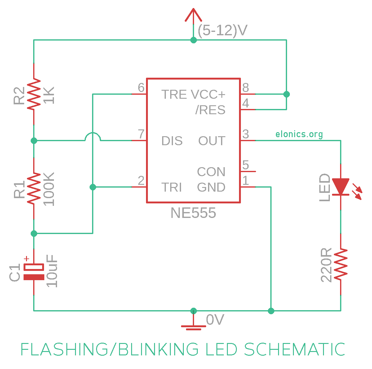
So I will be building a circuit that blinks and LED from this schematic I found. I am avoiding reading the instructions for the circuit and I'm going to build it solely based off the schematic. After I build the circuit I will be attempting to hack the circuit and change things to see what works. I will also be linking pictures of the things I am talking about so you can see what I mean.
Initially looking at this schematic was tough. I know how to read them and what the symbols for each component were but I have never attempted to replicate a schematic onto a breadboard. Mostly the confusing parts of this schematic for me were the connections to pin 7 on the IC, and the way resistor 1 and resistor 2 are supposed to connect, and it shows on the breadboard this looks like a mess. The result of this circuit is that the LED is constantly on.
It was pointed out to me I was interpreting the schematic wrong. While I was looking at it before I took a weird approach where I started building from the center out. The new approach I took was in this case was building from the top since that's where power comes in. This approach resulted in a easier to follow schematic, but also one that works, and it looks a lot cleaner than the last!
Examining the LED
The first change I decided to make was going from a standard size LED to one of the bigger LED's. weirdly enough I thought I was going to have to use a different resistor but it worked without problems. Looking at the LED I thought maybe I can add more, so I took a wire and branched it off to the side where there was open space and replicated the output of LED and a 220 ohm resistor and branched off with another wire and added another big LED and 220 ohm resistor and they're all blinking together. If I use a resistor to connect the LED to the next instead of a wire the light from the LED is dimmer, and I also tried using the resistors in place of the wire while keeping the original 220 ohm resistors where they were, 1k ohm resistor completely stopped the LED from lighting up and a 22k ohm resister left it dim as well. I put the wire back instead and it's laid out like before.
Examining the Capacitor
I thought about trying to put a delay in between the LED's although I don't think I really have too many components to work with unless I want to build it myself. The first thought I had was that I could maybe use a capacitor to maybe cause some delay, so I replaced the wire connecting the red LED to the yellow LED and the yellow LED started glowing but with each pulse the light became dimmer when a bigger capacitor was used, but when a smaller cap was used it either never lit up or only lit up briefly. Next was to change the LED that the circuit started with in the schematic which was a 10uF 25v capacitor. When I took out the capacitor I noticed the blinking stopped, and changing the value of the cap changed the speed at which the LED's blinked. I cant really tell for sure but I believe it also effected the brightness of the LED's, but that could also just be a mistake on my part.
Learning more about the 555 timer IC
Without the 555 timer this circuit doesn't work. I'm sure there are probably circuits I can look into in order to get a similar result, but that aside I don't really know anything about this IC that is driving this whole project. In order to fix that I watched this video by GreatScott. With GreatScotts video I feel like I understand HOW it works but I'm still struggling over here on the WHY it works. Although that's probably due to the questions I'm asking myself after watching the video on how they work and how they're built, what are flip-flops and comparators? These IC's are needed for this circuit to function so what are they? Not knocking on GreatScott I love his channel, and he has some of the best content when it comes to electronics and he probably has videos on the subjects I struggled understanding in the video, but in this case I feel like explaining each of these components on a basic level and how they work with the 555 would have helped me better personally. I was recommended by YouTube another 555 video that Element14 Presents made. To start off, this video helped me understand a little bit better how its all coming together. I'm starting to understand how the 555 works on the inside, most of my confusion is originating from my inexperience and that will fade with more exposure to the content. Something I find interesting is that there are different modes that are determined based on how the circuit is setup. In the video she mentions that there are 3 modes that being astable, monostable, and bistable, the original circuit diagram uses the astable mode.
The questions about the components from GreatScott's video were answered in this video. Starting with the comparator in her words "A comparator is a component that compares the voltages at its inputs, and outputs a digital signal that indicates which of the inputs is larger. If the positive input is larger the output is high and if it's negative is larger then it's low". I feel like that was a great straight forward description and helped me understand what the 555 is trying to do better. The way I understand the SR flip-flop is a circuit that keeps track of state using its inputs as switches, and is straight forward with its function, and in the case of the 555 is how the circuit itself knows if it's on or off.
Lets not say that the video didn't leave me with questions. Most of my questions revolve around the pins, and the pins for the 555 are mostly straight forward to me at the moment, with the exception of a few but I will touch on that. Pin 1 is used to connect to ground, pin 8 is used to supply Vcc to the IC; Vcc being the voltage we supply the IC, pin 7 is used to discharge the capacitor of the charge its stored; which is what restarts the cycle so the capacitor can fill up again, and pin 3 is where the signal outputs from the IC. However my problems are with pins 2, 4, 5, and 6; starting with pin 4 which is supposed to be the reset pin, but when experimenting with this pin I unplugged it while it was on and nothing happened, it just kept working, so I tried wiring it up to a switch like some of the schematics I've seen and when flipped on or off nothing happened once again, so the confusion that has built up is because I'm not sure as to why it's not functioning. Next is pin 5 which is a control pin and is connected to the comparator that pin 6 is connected to. My confusion is that I dont exactly understand its purpose, in the IC it's supposed to overwrite the output to the comparators negative terminal, but why does it need to be overwritten, how often is it getting overwritten, and if it's a lot whats the point of the original signal? Pins 6 and 2 are weird because they work together in order to control the logic for the flip-flop in the circuit, so most of the confusion just comes from not immediately knowing what the high and low signals do to each pin.
You'll need to look at the schematic for the 555 for this to make any sense, but a really simple question I was left with was if you look from pin 8 to pin 1 there are 3 resistors and in between the first and second resistor there is a connection leading to the negative input terminal of comparator 2 and another connection that is in between the second resistor and third resistor leading to the positive input terminal of comparator 1. Why is the first connection's resistance 2/3 the voltage and the second's is 1/3? Well looking into resistance more I came across whats called voltage dividers and here is a schematic for one. Looks familiar doesn't it? My issue was that I forgot resistors also divided the voltage, so when you have two connected to eachother in series the connection point that can be made in the middle will be divided based on the values of the resistors and thats all a voltage divider is, two resistors connected in series with a connection in between them that acts as the output. This video by Afrotechmods helped visualized how they worked pretty quick.
The next goal I have is to create a delay between each LED so they blink one after the other. This was surprisingly easy, hooray for the internet because I found this page about a two component delay circuit with a schematic. Still new to schematics so took some trial and error getting it to function. I had to swap out resistors and capacitors until I noticed the difference. However the to get a delay that was noticeable I needed a bigger resistor so now the LED is very dim, so what do I do about that? Nothing really, when the second LED's delay starts the 555 timer is outputting a LOW signal thus its not powering the rest of the circuit, so during that time the only reason the LED is getting power is because the capacitor in the delay circuit is discharging what it had stored and never really getting to take advantage of the HIGH signal output from the 555.
I had a lot of fun with this project, diving into a really simple project really took a turn I didn't really expect to dive as deep as I did, but it was really educational for me. I learned how to use some of my equipment better just from adjusting the probes and observing the output, debugging the circuit is something I'm still getting used to but will come with experience, reading schematics was something I could already do, but replicating to a breadboard was a lot harder at first than I initially thought it would be, and now I have a much better idea on how the 555 timer works and the components that make it work. Next time I will be documenting with more pictures as well, since I am still adjusting to my equipment I was a little too focused and didn't take as many pictures. I want to also mess around with counter IC's that will let me achieve that goal of making LED's blink one after the other, like I attempted to do near the end of this post.
Thanks for reading!